| « Ode to the Anagramic Poem | Segmented Computer Memory » |
The "Little Planet" effect is the colloquial name often used to refer to the mathematical concept of a stereographic projection. The end result is quite impressive, especially considering the little amount of code that is actually required to create the image. All that is required is a panoramic image with a 360° view from side to side, or a photo-sphere, such as used with Google Earth to provide an immersive view of a location.

Stereographic Projection
This is a mapping from a spherical position onto a plane. You will commonly see this type of projection in cartography; two examples are mapping the earth and planispheres (celestial charts). This projection is useful because it is not possible to map from a sphere to a plane without some type of distortion. The stereographic projection preserves angles and distorts areas. This trade-off is preferred for navigation, which is typically performed with angles.
The projection is typically performed from one of the poles. However, it can originate from any point on the sphere. For simplicity, unless otherwise stated I will refer to projections that originate at the North Pole of the sphere. For a unit-sphere located at the origin, this would be at \(\matrix{[0 & 0 & 1]}\)
The distortion of the image depends on the placement of the plane relative to the sphere. The upper hemisphere exhibits most of the distortion. The distortion becomes more extreme the closer the point in the sphere's surface approaches the origin of the projection. The projection extends to infinity as the projection's origin is undefined.
If the plane bisects the sphere at the equator, the lower hemisphere will be projected within an area the size of the circumference of the sphere, and the upper hemisphere is projection on the plane outside of the sphere.
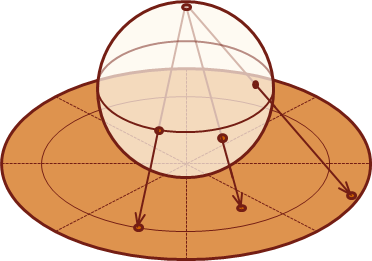
When the plane is located at the surface of the sphere, opposite from the projection's origin, the lower hemisphere will project over an area that is twice that of the sphere's equator. The image below illustrates this configuration.
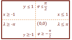
We can reference any point on the spheres surface with two angles representing the latitude \(\phi\) and longitude \(\lambda\), where:
\(-\pi \lt \lambda \lt \pi, -\cfrac{\pi}{2} \lt \phi \lt \cfrac{\pi}{2} \)
The following image is a scaled down version of the panorama that I used to generate the stereographic projection of the Golden Gate Bridge at the beginning of the article. Normally we would index the pixels in this image with two variables, \(x\) (width) and \(y\) (height).
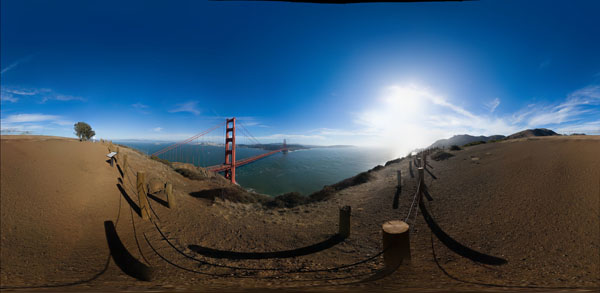
We can simplify the math to map a full-view panorama to a sphere by normalizing the dimensions for both the sphere and our surface map; that is, to reduce the scale to the unit scale of one. This means we will perform the surface map operation on a unit-sphere, and the dimensions of our panorama will then span from: \(-1 \lt x \lt 1, -1 \lt y \lt 1\).
The following image shows how the coordinate system from the sphere maps to the image:
Project the sphere onto the Plane
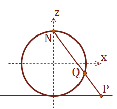
We will create a ray, to calculate the projection of a single point from the sphere to the plane. This ray begins at the projective origin, passes through the sphere and points at any other point on the surface of the sphere. This ray continues and will intersect with the projective plane. This intersection is the point of projection. Alternatively, we can calculate the intersection point on the sphere's surface, given a ray that points between the projective origin and the projection plane. This demonstrates that the stereographic projection is a bijective operation; there is a one-to-one correspondence for the values on both surfaces.
The diagram below depicts the projection in two-dimensions:
If \(\lambda_0\) as the central longitude and (\phi_1\) as the central latitude, this relationship can be stated mathematically as:
\( \eqalign{ u &= k \cos \phi \sin(\lambda - \lambda_0) \cr v &= k [ \cos \phi_1 \sin \phi - \sin \phi_1 \cos \phi \cos(\lambda - \lambda_0)]\cr & where \cr k &= \cfrac{2R}{1+ \sin \phi_1 \sin \phi + \cos \phi_1 \cos \phi \cos(\lambda - \lambda_0)} } \)
The term \(k\) determines where the projected plane is located.
Codez Plz
That is enough theory and explanation. Here is the code that I used to generate the stereographic projections of the Golden Gate Bridge and Las Vegas. The code presented below is adapted from a project I just completed that used the Computer Vision library OpenCV. The only important thing to note in the code below is that Mat objects are used to store images and pixels are represented with a type of std::vector. You should have no problem converting the pixel access operations from the code below to whatever image processing API that you are using.
If you do run into problems, leave a comment and I will help you work through porting the code.
First, here are two constants defined in the code:
C++
const double k_pi = 3.1415926535897932384626433832795; | |
const double k_pi_inverse = 0.31830988618379067153776752674503; |
There are three functions:
Main Projection
This function works by creating a ray between the projection origin and a pixel location on the projection plane. The intersection of the sphere's surface is calculated, which indicates the location to sample from the sphere's surface map. Because we are dealing with discrete, pixelated digital images, this sampling process creates visual artifacts. To help improve the smoothness of the image, we use a bilinear filter to average the values of four surrounding pixels of the sample location from the sphere.
C++
void RenderProjection(Mat &pano, long len, Mat &output) { | |
output.create(len, len, CV_16UC3) | |
long half_len = len / 2; | |
Size sz = pano.size(); | |
| |
for (long indexX = 0; indexX < len; ++indexX) { | |
for (long indexY = 0; indexY < len; ++indexY) { | |
double sphereX = (indexX - half_len) * 10.0 / len; | |
double sphereY = (indexY - half_len) * 10.0 / len; | |
double Qx, Qy, Qz; | |
| |
if (GetIntersection(sphereX, sphereY, Qx, Qy, Qz)) | |
{ | |
double theta = std::acos(Qz); | |
double phi = std::atan2(Qy, Qx) + k_pi; | |
theta = theta * k_pi_inverse; | |
phi = phi * (0.5 * k_pi_inverse); | |
double Sx = min(sz.width -2.0, sz.width * phi); | |
double Sy = min(sz.height-2.0, sz.height * theta); | |
| |
output.at<Vec3s>(indexY, indexX) = BilinearSample(pano, Sx, Sy); | |
} | |
} | |
} | |
} |
Calculate the Intersection
This calculation is an optimized reduction of the quadratic equation to calculate the intersection point on the surface of the sphere.
C++
bool GetIntersection(double u, double v, | |
double &x, double &y, double &z) | |
{ | |
double Nx = 0.0; | |
double Ny = 0.0; | |
double Nz = 1.0; | |
double dir_x = u - Nx; | |
double dir_y = v - Ny; | |
double dir_z = -1.0 - Nz; | |
| |
double a = (dir_x * dir_x) + (dir_y * dir_y) + (dir_z * dir_z); | |
double b = (dir_x * Nx) + (dir_y * Ny) + (dir_z * Nz); | |
| |
b *= 2; | |
double d = b*b; | |
double q = -0.5 * (b - std::sqrt(d)); | |
| |
double t = q / a; | |
| |
x = (dir_x * t) + Nx; | |
y = (dir_y * t) + Ny; | |
z = (dir_z * t) + Nz; | |
| |
return true; | |
} |
Bilinear Filter
The bilinear filter calculates a weighted-sum of the four surrounding pixels for a digital image sample.
C++
Vec3s BilinearSample(Mat &image, double x, double y) { | |
Vec3s c00 = image.at<vec3s>(int(y), int(x)); | |
Vec3s c01 = image.at<vec3s>(int(y), int(x)+1); | |
Vec3s c10 = image.at<vec3s>(int(y)+1, int(x)); | |
Vec3s c11 = image.at<vec3s>(int(y)+1, int(x)+1); | |
| |
double X0 = x - floor(x); | |
double X1 = 1.0 - X0; | |
double Y0 = y - floor(y); | |
double Y1 = 1.0 - Y0; | |
| |
double w00 = X0 * Y0; | |
double w01 = X1 * Y0; | |
double w10 = X0 * Y1; | |
double w11 = X1 * Y1; | |
| |
short r = short(c00[2] * w00 + c01[2] * w01 | |
+ c10[2] * w10 + c11[2] * w11); | |
short g = short(c00[1] * w00 + c01[1] * w01 | |
+ c10[1] * w10 + c11[1] * w11); | |
short b = short(c00[0] * w00 + c01[0] * w01 | |
+ c10[0] * w10 + c11[0] * w11); | |
| |
return make_BGR(b, g, r); | |
} |
...and a helper function:
C++
Vec3s make_BGR(short blue, short green, short red) | |
{ | |
Vec3s result; | |
result[0] = blue; | |
result[1] = green; | |
result[2] = red; | |
| |
return result; | |
} |
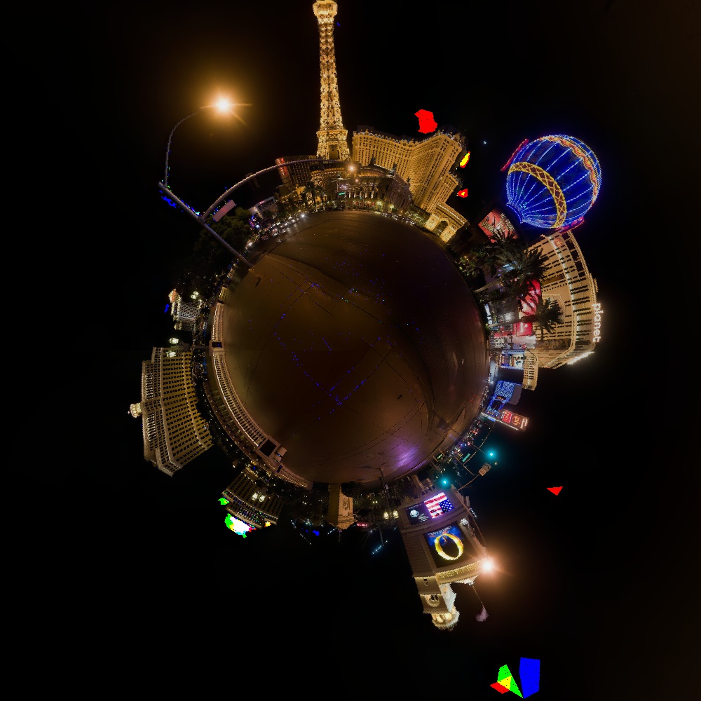
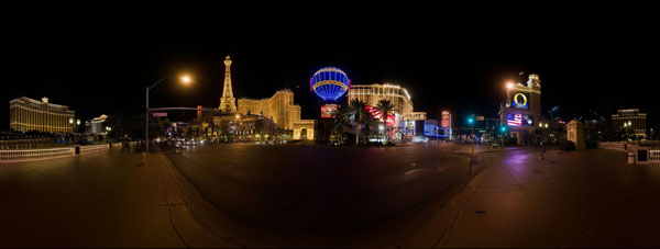
Here is another sample of a stereographic projection and the panorama that I used to create it:
Summary
The stereographic projection has been known and used since the time of the ancient Greeks. It was heavily used in the Age of Exploration to create maps of the world where the distortion was applied to distances, and the relative angles between local points is preserved. When it is applied to full-view panoramas a neat effect is created called, "The Little Planet Effect." With just a little bit of theory and some concepts from computer graphics we were able to turn this concept into code with less than 100 lines of code.

Recent Comments